DMX Wiring Fundamentals
DMX512, a standard for digital communication in lighting, transmits data via a balanced three-wire system. Two wires carry data signals, while one serves as a common reference, minimizing external interference. Proper cabling and termination are crucial for reliable signal transmission.
Understanding DMX Signal Transmission
DMX512, the standard protocol for digital lighting control, relies on a robust, balanced transmission system. This system uses a three-wire configuration⁚ two data lines and a ground. The balanced nature of the system significantly reduces the impact of electromagnetic interference (EMI) which is common in electrical environments. This is crucial for maintaining signal integrity over longer cable runs, ensuring reliable communication between the DMX controller and lighting fixtures. The signal itself is a serial data stream, transmitting commands for controlling various aspects of lighting devices, including intensity, color, and special effects. Understanding the principles of serial communication and the importance of proper grounding is paramount to successful DMX implementation. Incorrect grounding can lead to data corruption, erratic behavior, and ultimately, system failure. Using shielded cables specifically designed for DMX transmission further mitigates the risk of signal degradation, ensuring a smooth and consistent performance.
DMX Cable Types and Specifications
Selecting the correct DMX cable is vital for reliable signal transmission. While 5-pin XLR connectors are the standard, 3-pin XLRs are also frequently used, particularly in modern systems where only two data lines and a ground are necessary. The cable itself should be specifically designed for DMX/RS-485 networks, possessing a characteristic impedance of 120 ohms to minimize signal reflections. Standard building wire is unsuitable due to its higher capacitance and impedance mismatch. Shielding is critical to protect against EMI, ensuring clean signal transmission, especially in environments with significant electrical noise. The quality of the shielding directly impacts the reliability of the DMX signal over long distances. Cable length is also a factor; while theoretical limits exceed 3000 feet, it’s recommended to keep runs under 1500 feet for optimal performance and to avoid signal attenuation. Using high-quality, appropriately specified DMX cables is a fundamental aspect of ensuring a robust and dependable lighting control system. Failure to do so can result in signal loss, data corruption, and unpredictable fixture behavior.
Importance of Proper Termination
Proper termination of DMX lines is crucial for preventing signal reflections and ensuring reliable data transmission. These reflections, caused by impedance mismatches at the end of the cable, can corrupt data and lead to erratic fixture behavior, including flickering or unexpected color changes. The standard termination method involves a 120Ω resistor connected across the data lines (+ and -) at the very end of the DMX run. This resistor matches the characteristic impedance of the cable, absorbing any reflected signals and preventing them from interfering with the main signal. Without proper termination, signal integrity degrades, particularly over longer cable runs. The result can be data loss or corrupted commands, leading to malfunctioning lights and frustration. Incorrect termination can also cause damage to DMX controllers or lighting fixtures. Therefore, always use the correct 120Ω resistor and ensure it’s properly connected across the data lines at the far end of the DMX network. This simple step ensures reliable communication and prevents costly troubleshooting down the line.

DMX Wiring Configurations
DMX wiring involves various setups, from simple daisy chains connecting fixtures sequentially to more complex networks using splitters and mergers for distributing the signal efficiently to numerous devices. Understanding these configurations is key to successful DMX implementation.
Daisy Chaining Multiple Fixtures
Daisy chaining is a straightforward DMX wiring method where lighting fixtures are connected in a series. The DMX output of one fixture is linked to the DMX input of the next, creating a single line. This method simplifies wiring, especially for smaller installations. Begin at the DMX controller, connecting its output to the input of the first fixture. Subsequently, connect the output of each fixture to the input of the following one. This creates a continuous signal path. The final fixture in the chain requires termination with a 120Ω resistor to prevent signal reflections and ensure data integrity. Remember to use appropriate DMX cable—specifically designed for this application with a 120Ω impedance—to maintain signal quality and prevent signal loss or distortion. Using incorrect cabling can lead to malfunctions or complete failure of the system. Always ensure proper grounding to minimize the impact of electrical noise. Thoroughly check all connections before powering on the system to prevent potential short-circuits or damage to equipment. Carefully plan your daisy chain layout to minimize cable length, thereby enhancing signal strength and reliability.
Using DMX Splitters and Mergers
DMX splitters distribute a single DMX signal to multiple outputs, allowing control of numerous fixtures from a single source. This is particularly useful when managing a large number of lights, avoiding excessively long daisy chains. High-quality splitters are crucial; inferior ones can introduce signal noise or attenuation. Always choose splitters with sufficient capacity for your setup, ensuring each output receives a clean signal. Conversely, DMX mergers combine multiple DMX signals into one, often used to consolidate outputs from different controllers or sections of a lighting system. When using mergers, be mindful of potential address conflicts. Ensure each incoming DMX universe has unique address ranges to prevent data collisions and unpredictable behavior. Properly terminated cables are essential for both splitters and mergers. Incorrect termination can lead to signal degradation and unreliable operation. Remember to check for signal strength at each output of the splitter and each input of the merger using a DMX tester. This ensures all fixtures receive sufficient signal quality for consistent operation.
Wiring DMX to Different Fixture Types
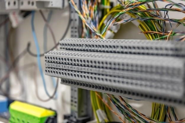
Connecting DMX to various fixtures involves understanding their specific input types. While many use standard 3-pin or 5-pin XLR connectors, some utilize alternative methods like terminal blocks. Always consult the fixture’s manual for the correct wiring method. Incorrect connections can damage the fixture or the DMX controller. For XLR connectors, ensure proper pin assignments⁚ pin 1 (ground), pin 2 (data -), and pin 3 (data +). 5-pin XLRs incorporate additional return channels, but the core data transmission remains the same. When working with terminal blocks, carefully match the wiring diagram in the fixture’s manual to avoid short circuits or incorrect signal polarity. Pay close attention to the positive and negative data lines, as inverting them will prevent the fixture from functioning correctly. Using the wrong cable type can also lead to signal loss or interference. DMX cables should have a characteristic impedance of 120 ohms and low capacitance. Improper cable choices can result in signal degradation, especially over longer distances. Always visually inspect your connections before powering on equipment to prevent damage from incorrect wiring.

Troubleshooting DMX Wiring
Addressing DMX issues often involves checking cable connections, ensuring proper termination, and verifying the DMX controller settings. Inspect for loose connections, damaged cables, and incorrect pin assignments. Use a DMX tester to verify signal transmission and identify signal breaks or shorts within the wiring.
Common DMX Wiring Problems and Solutions
One frequent issue is signal loss or intermittent operation. This often stems from faulty cabling, employing incorrect cable types (like standard building wire instead of DMX-rated cable), or poor termination. Solutions include replacing damaged cables with DMX-specified, low-capacitance, 120Ω impedance cable, and ensuring proper termination with a 120Ω resistor at the end of the daisy chain. Another problem arises from incorrect pin assignments in XLR connectors; double-check pinouts against the DMX standard. Improper grounding can also lead to interference and signal noise. Make sure all grounds are properly connected throughout the system to eliminate ground loops. Finally, exceeding the recommended cable length (1500 feet is suggested) can result in signal degradation. Break long runs into shorter segments using DMX splitters to maintain signal integrity. Always utilize a DMX signal tester to diagnose and isolate these issues efficiently.
Testing and Verifying DMX Connections
Verifying DMX connections requires a systematic approach. Begin by visually inspecting all cables for damage, ensuring proper termination with a 120Ω resistor at the chain’s end. Loose connections are a common culprit; firmly secure all XLR connectors. Utilize a DMX tester to analyze signal strength and identify breaks in the line. These testers often display signal levels and identify faults along the data path. A simple method involves setting fixtures to different addresses and observing their response to control signals from the console. Check each fixture individually to confirm that it’s receiving the correct DMX address and responding appropriately. If using a DMX software interface, monitor data packets for errors or inconsistencies. Systematic troubleshooting, starting from the controller and progressing through each fixture in the chain, helps pinpoint problem areas effectively. Remember that a multimeter can check continuity and identify short circuits in the cables, assisting in quick diagnosis.